 EN
EN

Why Greenhouses Need Mechanical Ventilation at All
A closed greenhouse on a sunny day heats faster than almost any other agricultural structure. Solar radiation passes through the glazing, is absorbed by soil, crop and structure, and re-radiates at a wavelength the glazing does not release. Without ventilation, interior temperature climbs past anything the crop can tolerate within hours.
Ventilation also manages humidity and CO₂. Transpiring plants push interior humidity up, and sustained high humidity invites fungal disease; a dense crop in a sealed house can draw down CO₂ until photosynthesis slows. Opening vents addresses all three, which is why vent control sits at the centre of greenhouse climate management rather than at its margins.
The question is mechanical: how do you open several hundred square metres of vent sash, reliably, thousands of times a season, in a wet environment? For commercial multi-span houses, the dominant answer is rack and pinion greenhouse ventilation.
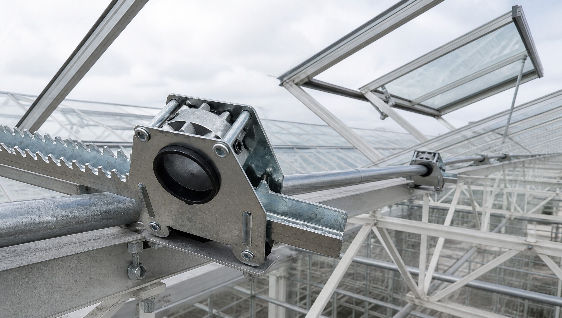
The Five Components of a Rack and Pinion Vent System Gear Motor
The gear motor is the power source — an electric motor with an integral reduction gearbox. The reduction matters more than the motor. Vent sashes need high torque at very low speed, because you are moving a large, wind-loaded panel slowly and under control. Output speeds in these systems are typically a few revolutions per minute, not hundreds.
The gearbox also usually provides a self-locking or high-resistance characteristic, so a vent left partly open does not get driven closed by wind pressure pushing back through the drivetrain.
Drive Shaft
The drive shaft is a steel tube or bar running the length of the vent bay, supported at intervals by bearing housings fixed to the greenhouse frame. It is the distribution element: one motor turns one shaft, and that single rotation is delivered simultaneously to every vent position along the bay.
This is the architectural decision that makes the system economic. A 60-metre bay with twenty vent positions does not need twenty motors. It needs one motor, one shaft, and twenty conversion points.
Pinion
The pinion is the small gear clamped onto the drive shaft at each vent position. It is where rotation becomes available as motion at that specific vent.
In practice the pinion is rarely a bare gear on the shaft. It sits inside a rack and pinion drive unit — a steel frame that supports the pinion, holds the rack in mesh, and clamps to the shaft. That framing is what makes the conversion reliable under load, which we come back to below.
Gear Rack
The rack is a toothed steel bar. Its teeth mesh with the pinion, and because the rack cannot rotate, the pinion's rotation drives the rack along its length. This is the actual conversion: rotary motion in, linear motion out.
Greenhouse racks are commonly straight-cut (spur) rather than helical. Spur teeth generate no axial thrust — the force stays in the plane of travel instead of trying to push the pinion sideways along the shaft. For a component that must hold position on a shaft through thousands of cycles, that matters more than the marginal smoothness a helical form would offer. See our galvanized greenhouse gear rack for the tooth form used in these systems.
Push Rod and Support Arm
The rack rarely bolts straight to the vent sash. A push rod transfers the rack's linear travel to a support arm hinged to the sash, and the support arm converts that push into the angular swing of the vent opening.
This linkage is doing real work. It changes the direction of the force, provides mechanical advantage at the start of the stroke where the sash is heaviest to break free, and lets the rack run in a convenient straight line while the sash swings through an arc.
The Opening and Closing Principle, Step by Step
To open:
1. The climate controller calls for ventilation and energises the gear motor.
2. The motor's output shaft turns slowly at high torque.
3. The drive shaft rotates along the full length of the bay.
4. At each vent position, the pinion clamped to the shaft rotates with it.
5. The pinion teeth engage the rack teeth and drive the rack linearly.
6. The rack pushes the push rod.
7. The push rod drives the support arm, which swings the sash open.
8. The controller stops the motor at the target opening position.
To close, the motor reverses and the same chain runs backwards — the rack retracts, the support arm pulls the sash down, and the vent seals against its frame.
The whole chain is mechanically positive. There is no hydraulic fluid to leak, no pneumatic pressure to lose, no cable to stretch. Every element is a direct mechanical connection, and the vent position at any moment is a direct function of how far the motor has turned. That determinism is why controllers can hold a vent at 30% opening and trust that it is actually at 30%.
Understanding Rack Travel
Rack travel is the linear distance the rack moves from fully closed to fully open. It determines how far your vent actually opens, and it is set by two things: the pinion's pitch circumference, and how many turns the drive shaft makes.
Every full rotation of the pinion advances the rack by one pitch circumference. A larger pinion moves the rack further per revolution but demands more motor torque for the same load, because the pinion radius acts as a lever arm against the motor. A smaller pinion is easier on torque but needs more shaft revolutions for the same opening.
Two practical consequences follow:
The rack must be long enough for the full stroke plus engagement. A rack sized exactly to the travel distance runs out of teeth at the end of the stroke, and the last teeth carry the entire load at the worst possible moment. Sizing this correctly is covered in how to select the right rack.
Travel must be limited before it reaches the mechanical end. Limit switches or controller position limits should stop the motor before the rack reaches the end of its teeth. Relying on the mechanism to stall against its own limits is how teeth get sheared.
Roof Vent Systems
Roof vents run along the ridge, and on Venlo-type and similar truss structures they are the primary ventilation route. Hot air rises, collects at the ridge, and exits through the roof vent — the most thermally effective place to put an opening.
Mechanically, roof vents are the more demanding case. The sash lifts against gravity, so the mechanism carries the panel weight throughout the stroke. More significantly, an open roof vent presents a raised surface to the wind, and wind load can exceed the sash's static weight considerably. The drive components are sized for that wind case, not for the weight.
Roof positions also see the most condensation. Warm humid air collects at the ridge, and metal surfaces there run through a wetting and drying cycle every night — which is why galvanized components are standard rather than optional there.
Because one shaft drives a whole row, all vents in a bay open together. Each drive unit must therefore be clamped to the shaft in the same phase, so the vents track as a set. A vent clamped out of phase leads or lags its neighbours and takes a disproportionate share of the load at the ends of the stroke.
Side Vent Systems
Side vents open in the sidewall and work with roof vents to establish cross-flow — cool air entering low through the sidewall, warm air leaving high through the ridge. That vertical air movement is more effective at removing heat than either opening alone.
Side vent mechanisms follow the same rotary-to-linear principle but face different conditions. Gravity load is lower, since the sash swings rather than lifts. Wind exposure is more direct but acts on a smaller effective area. The real difference is contamination: sidewall components sit close to ground level and collect soil splash, irrigation overspray and dust.
That contamination is the dominant maintenance factor. Debris packed into the tooth roots is the most common cause of stiff or jerky side vent operation, and it usually shows up long before there is any measurable wear on the teeth themselves.
Some sidewall designs use a vertical opening arrangement where the sash climbs a guide rail, with the rack and pinion driving that vertical motion. The conversion principle is identical; only the geometry of the linkage changes.
Why Rack and Pinion Instead of a Push-Pull Cylinder
Alternative vent drives exist — pneumatic cylinders, electric linear actuators, cable and winch arrangements. Rack and pinion dominates commercial greenhouse ventilation for structural reasons.
One motor serves many vents. A linear actuator moves one sash; a rack and pinion shaft serves an entire bay from a single drive. Across a multi-hectare site the difference in motor count, wiring and control points is substantial.
Position is deterministic. Rack position is a fixed function of shaft rotation, with no slack to accumulate. Cable systems stretch; pneumatic systems drift with pressure.
Stroke length is not constrained by the actuator. A cylinder's stroke is limited by its own body length. Rack travel is limited only by rack length.
It tolerates the environment. No seal to perish, no fluid to contaminate, no pressure line to fatigue. A galvanized steel rack and pinion in a steel frame is about as simple as a powered mechanism gets, and simplicity is what survives fifteen years of daily condensation.
Where These Systems Fail in Practice
Understanding the failure modes tells you more about the mechanism than the specification sheet does.
Loss of engagement depth. Under wind load the rack tends to lift away from the pinion, reducing how deeply the teeth mesh and concentrating force on the tooth tips. This is precisely what the guide pins fitted either side of the pinion in a proper drive unit prevent — they bear on the back of the rack and hold it in mesh exactly when load is highest.
Misalignment. A rack not parallel to its travel direction binds partway through the stroke. Installers sometimes respond by increasing motor torque, which converts a geometry problem into a broken tooth.
Sag on unsupported spans. A long rack without intermediate support deflects under its own weight, losing engagement depth at mid-travel while remaining correct at both ends.
Mismatched tooth form. A spur rack running against a helical pinion produces point contact instead of line contact across the tooth face. It appears to work on installation and fails within a season. Selecting the right geometry is covered in how to select the right rack.
Debris in the tooth root. The most common cause of stiff operation, and the easiest to fix. In a dusty house, grease traps grit and accelerates wear rather than reducing it.
FAQ
Q: How much torque does a greenhouse vent gear motor need?
It depends on sash weight, vent count per shaft, pinion size and the design wind load for your site — not on a single published figure. The wind case usually governs, not the static weight. Have it calculated for your specific structure rather than assumed from a similar house.
Q: Can one motor drive both roof and side vents?
In practice they are driven separately. Roof and side vents are controlled independently because the climate strategy calls for different opening positions at different times — you often want sidewalls open while the roof is partly closed, or the reverse in wind.
Q: How far should a greenhouse roof vent open?
That is a climate control decision rather than a mechanical one, and it varies with crop, outside temperature and wind. What matters mechanically is that the system can reach full opening reliably and hold any intermediate position without drifting.
Q: What is the difference between rack travel and vent opening angle?
Rack travel is the linear distance the rack moves. Opening angle is the angular swing of the sash. The linkage geometry — push rod length and support arm pivot position — converts between them, and the relationship is not linear across the stroke.
Q: Why are greenhouse racks galvanized instead of painted?
Paint fails at the tooth flanks first, because that is where metal-to-metal contact occurs every cycle. Once the coating is worn through at the contact point, corrosion starts exactly where the load is carried. Zinc coating handles the condensing environment without depending on an intact film.
Q: Can a rack and pinion vent system be operated manually if the power fails?
Depends on the gearbox. Many greenhouse gear motors include a manual override or hand-crank facility for exactly this reason — a house with no ventilation on a sunny day loses a crop quickly. Confirm this when specifying the motor.
Conclusion
A rack and pinion greenhouse ventilation system is a chain of straightforward conversions: electrical energy becomes low-speed high-torque rotation at the gear motor, that rotation is distributed along the bay by the drive shaft, each pinion converts it to linear rack travel at its vent position, and the push rod and support arm turn that travel into the swing of the sash.
Nothing in the chain is complicated on its own. What makes the system work over a fifteen-year service life is that each conversion stays properly engaged — the pinion clamped securely and in phase on the shaft, the rack held at full tooth depth by the guide pins, the whole assembly aligned so nothing binds partway through the stroke, and zinc coating on every steel surface exposed to nightly condensation.
When these systems fail, it is rarely because the concept was inadequate. It is because a rack was installed out of line, a tooth form was mismatched, or debris was left packed in the tooth roots for three seasons.
