EN
EN

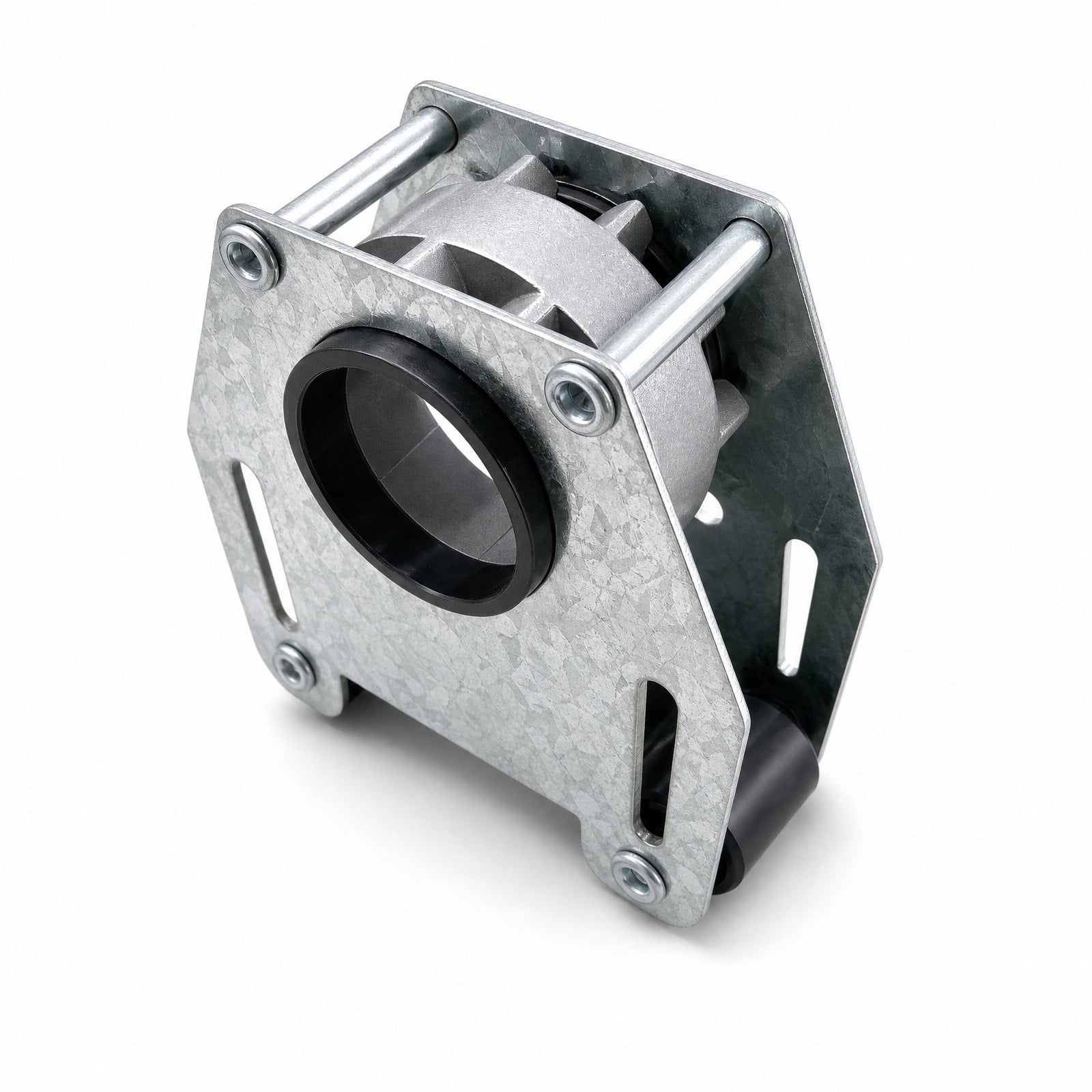
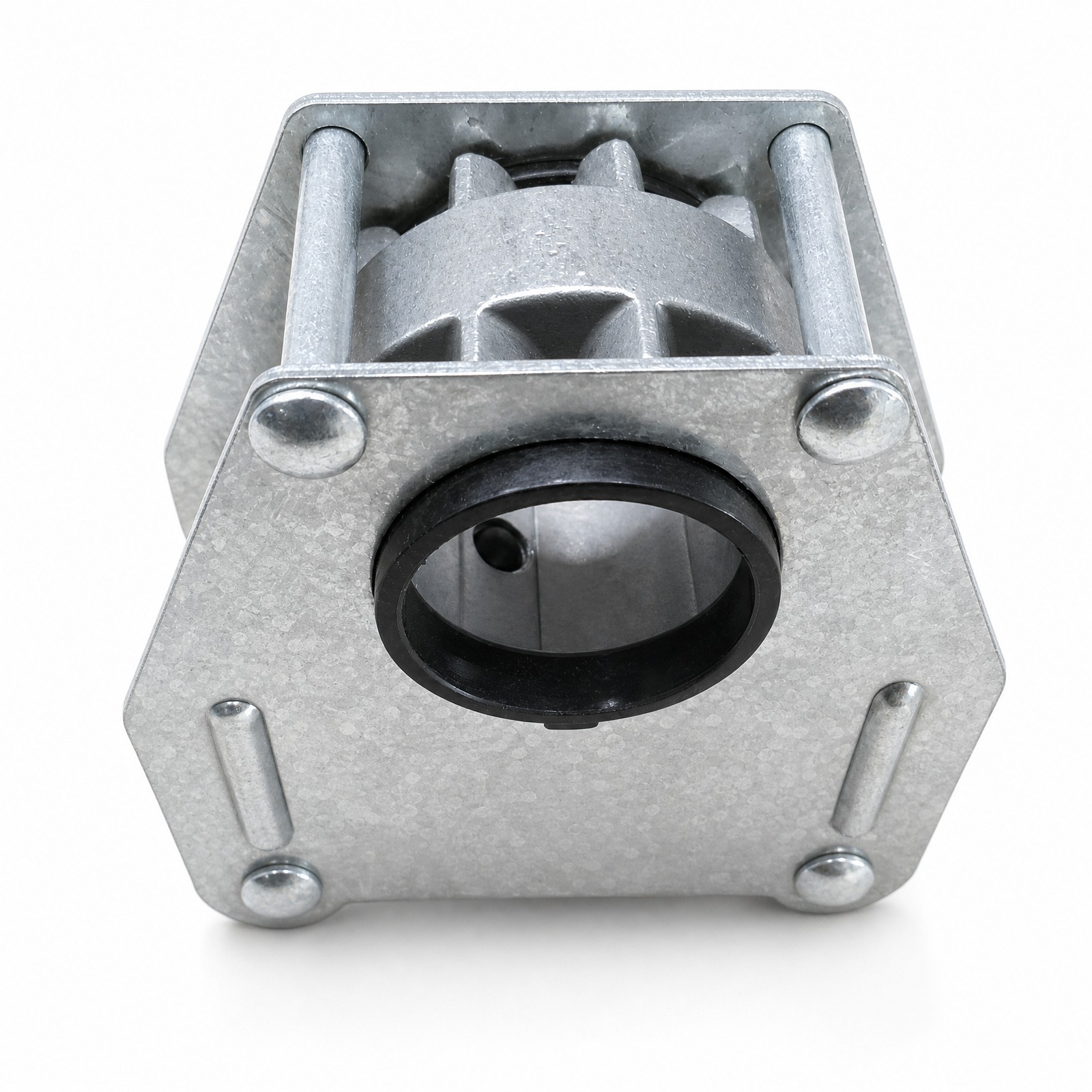
A galvanized steel drive unit that houses the pinion gear in a greenhouse ventilation drive system. The unit clamps onto the drive shaft with a set-screw bush, and the matching rack passes through its channel where guide pins and rollers hold the rack in constant mesh. Supplied as a standard part, normally quoted together with the rack.
In a greenhouse window opening system, the drive shaft carries rotation down the length of the vent bay — but rotation alone does not open anything. The drive unit is where that rotation is converted and, just as importantly, where the conversion is held in place.
The unit is built from galvanized steel pressings, with two side plates riveted together to form a rigid frame. Between them sits the pinion gear, supported so it stays on axis under load. The matching rack passes through a C-shaped channel in the back of the frame and meshes with the pinion. Two guide pins run parallel to the pinion axis, one on each side, bearing against the back of the rack. Their job is specific: when the vent loads up under wind, the rack tries to lift away from the pinion, and the guide pins stop that lift. Without them, tooth engagement gets shallower as load increases — exactly when you need it most.
The unit clamps onto the drive shaft through a black engineering-plastic bush locked by a set screw. This is the detail that matters on a multi-vent run: the timing of each vent relative to the shaft is set by where you clamp the unit. Loosen the set screw, rotate the unit to the position you want, retighten, and that vent's stroke is phased to match its neighbours.
Two plastic guide rollers are fitted at the lower corners of the frame. They bear against the mounting structure so the unit tracks cleanly rather than scuffing steel against steel. Two slotted mounting holes on the face of the frame allow the unit's position to be adjusted during installation — a practical concession to the fact that greenhouse steelwork is rarely dimensionally perfect on site.
At 0.42 kg per piece, the unit is light enough to be positioned and adjusted one-handed on a ladder, which is how it is usually installed.
For the full force path from gear motor through to vent sash, see greenhouse ventilation basics.
• Enclosed pinion in a riveted steel frame — the pinion is supported between two galvanized side plates rather than running exposed on the shaft.
• Guide pins on both sides of the pinion — hold the rack against the pinion so engagement depth does not reduce when the vent loads up.
• Set-screw plastic shaft bush — clamps to the drive shaft and allows each vent's phase to be set independently along a shared shaft.
• Two plastic guide rollers — the unit tracks against the mounting structure without metal-to-metal scuffing.
• Slotted mounting holes — installation position is adjustable, which absorbs the tolerance of as-built greenhouse steelwork.
• Galvanized throughout — for permanent service in a humid, condensing environment.
• Standard part — a stock item, not a one-off fabrication, so lead times and replacement supply are predictable.
Greenhouse Rack and Pinion Drive Unit — Confirmed Specifications
| Product Type | Greenhouse rack and pinion drive unit (pinion housing) |
| Frame Construction | Galvanized steel pressings, riveted assembly |
| Pinion Type | Spur pinion, enclosed within frame |
| Shaft Bush | Engineering plastic bush with set-screw clamping |
| Guide Pins | Two steel pins, one each side of the pinion |
| Guide Rollers | Two plastic rollers at lower frame corners |
| Rack Channel | C-shaped channel at rear of frame |
| Mounting | Two slotted holes, position adjustable |
| Surface Treatment | Zinc coated (galvanized) |
| Weight per Piece | 0.42 kg |
| Packing Quantity | 50 pieces per carton |
| Carton Dimensions | 22 × 27 × 34.5 cm |
| Product Status | Standard part |
| Drive Shaft Bore | Please contact us for detailed specifications |
| Overall Dimensions | Please contact us for detailed specifications |
| Pinion Module / Number of Teeth | Please contact us for detailed specifications |
• Frame and side plates — galvanized steel pressings. The spangled zinc finish is visible in the product photographs.
• Pinion — metal gear, enclosed within the frame.
• Shaft bush — black engineering plastic, with a metal set screw for clamping.
• Guide rollers — black plastic.
• Fasteners — zinc-plated rivets and screws.
The mix is deliberate. Steel carries the load; plastic goes where sliding contact and shaft clamping occur, because plastic-to-steel contact does not gall, does not need lubrication, and does not become a corrosion site in a permanently humid house.
Material grades and coating specification are confirmed per order.
Available Sizes
Supplied as a standard part in one configuration. Confirmed packing data:
• Weight per piece: 0.42 kg
• Packing: 50 pieces per carton
• Carton dimensions: 22 × 27 × 34.5 cm
Overall unit dimensions and the drive shaft bore diameter are confirmed per order. If you are matching an existing drive shaft, the bore diameter is the figure to confirm first — send your shaft diameter and we will confirm fit before quoting.
Gear Module
The unit houses a spur pinion. Please contact us for the module and tooth count.
This figure has to match the rack. Where the unit and rack are supplied together as a set, the match is confirmed before dispatch. Where the unit is being fitted to racks already installed in an existing house, send a photograph of the existing rack teeth against a ruler so the pinion can be confirmed against it.
Rack Length
Rack length is determined by the vent run, not by the drive unit. The unit accepts the matching rack through its channel; how long that rack needs to be depends on your required opening stroke and bay width. See module and length selection, or view the matching straight gear rack.
Pinion Compatibility
The pinion is enclosed within the unit and supplied as part of it — it is not sold as a loose gear. Compatibility therefore works in the other direction: you match the rack to this unit, or supply both together.
The pinion is a spur gear and runs with a spur rack. It will not mesh correctly with a helical rack. If your existing installation uses helical racks, tell us at enquiry stage — this unit is not the right part for that system, and we would rather say so than ship something that fails in the first season.
Surface Treatment
Zinc coated. Every steel element of the assembly — side plates, guide pins, rivets, screws — is zinc finished rather than just the visible outer faces. In a greenhouse the condensation reaches the inside of the frame as readily as the outside, so partial coating would simply move the corrosion where you cannot see it.
The plastic bush and rollers need no coating and are unaffected by humidity.
Mounting / Installation
1. Position the unit on the drive shaft. Slide it along to the vent position, with the shaft passing through the plastic bush.
2. Set the phase, then clamp. Rotate the unit to the orientation that matches the vent's required start position, then tighten the set screw against the shaft. On a run of vents driven by a single shaft, do this consistently — if one unit is clamped out of phase, that vent leads or lags the rest and takes a disproportionate share of the load at the end of the stroke.
3. Fix through the slotted holes. The slots give lateral adjustment. Use them to bring the unit into line with the rack path before final tightening, rather than forcing the rack to bend into an out-of-line unit.
4. Feed the rack through the channel. Check the rack sits at full tooth depth against the pinion, with the guide pins bearing on the back of the rack.
5. Confirm the rollers are in contact. The lower guide rollers should bear on the mounting structure.
6. Run the stroke by hand before powering up. Move the assembly through the full opening and closing range manually. Resistance at a specific point in the travel almost always means misalignment, not insufficient motor torque — and running the motor at it will damage teeth rather than solve it.
• Multi-span commercial greenhouses
• Venlo-type glass greenhouses
• Polycarbonate sheet greenhouses
• Vegetable production greenhouses
• Film-covered multi-span structures
• Retrofit of drive units on existing ventilation runs
Greenhouse Roof Vent Application
On roof vents, drive units are mounted at intervals along a shaft running the length of the ridge bay, with one unit per vent position. All units turn together, so all vents in the bay open simultaneously — which is exactly why the phase setting at the set screw matters. Consistent clamping across the run means the vents track together and share the wind load evenly.
Roof positions also see the heaviest condensation in the house, since warm humid air collects at the ridge. The enclosed frame gives the pinion some shelter from direct drip, and the plastic bush removes what would otherwise be a metal-to-metal sliding fit sitting in that environment.
Greenhouse Side Vent Application
On sidewall vents, the unit performs the same conversion but in a more contaminated position, collecting splash and dust that roof positions never see.
The practical advantage here is the enclosed frame: with the pinion sitting between two side plates rather than running open on the shaft, there is less direct ingress into the mesh. The plastic guide rollers also help — unlike a plain steel sliding face, they do not pack up with grit and seize.
Customization
Supplied as a standard part. The following can be discussed against project requirement:
• Drive shaft bore to suit your shaft diameter
• Pinion specification to match an existing rack
• Surface treatment for coastal or high-corrosion installations
• Supply as a matched drive unit and rack set
• Packing configuration for container consolidation
For retrofit, send photographs of the existing unit in position, the drive shaft diameter, and a photograph of the rack teeth against a scale.
Q: What drive shaft diameter does this unit fit?
Confirmed per order. Send your shaft diameter with the enquiry and we will confirm the bore before quoting — this is the first thing to check, because everything else can be right and the unit still will not go on.
Q: Is the pinion sold separately?
No. The pinion is enclosed within the unit and supplied as part of the assembly.
Q: How is the unit fixed to the drive shaft?
Through a plastic bush clamped by a set screw. Loosening the screw lets you rotate or reposition the unit, which is how each vent's phase is set on a shared shaft.
Q: What are the guide pins for?
They sit on either side of the pinion and bear against the back of the rack, keeping engagement depth constant instead of letting it reduce as the vent loads up. See greenhouse ventilation basics for the mechanics.
Q: How many units do I need?
One per vent position. A single drive shaft usually carries several units along a bay. Send your bay layout and vent count and we will work the quantity through with you.
Q: What is the packing configuration?
50 pieces per carton, carton dimensions 22 × 27 × 34.5 cm, 0.42 kg per piece.
Q: Can this replace a drive unit on an existing greenhouse?
Often yes, but it depends on the shaft diameter, the rack tooth pitch and the mounting arrangement. Send photographs of the existing installation and those three measurements.
Q: Does the unit need lubrication?
The plastic bush and rollers are designed to run without it. The pinion and rack mesh benefits from being kept clear of debris — in practice, cleaning the tooth gaps does more for service life than adding grease, which tends to trap grit in a dusty house.
Why Choose Us
• Manufacturer and exporter since 2008. Tianjin Haorongshengye Electrical Equipment Co., Ltd. designs and produces transmission components including sprockets, timing pulleys, roller chain, gears and gear racks, and exports them directly.
• Supplied as a matched set with the rack. Tooth engagement is verified as a pair before dispatch rather than discovered on site.
• Standard stock part. Predictable lead time and predictable replacement supply, including for a single failed unit mid-season.
• Confirmed packing data. 0.42 kg per piece, 50 per carton, 22 × 27 × 34.5 cm — real figures for your freight and duty calculation, given up front.
• We state what is unconfirmed. Where a dimension has not been verified against the physical part, this page says so rather than printing a number that might not hold.
• Retrofit support. Send photographs and shaft dimensions and we will confirm whether this unit fits your existing system before you order.