 EN

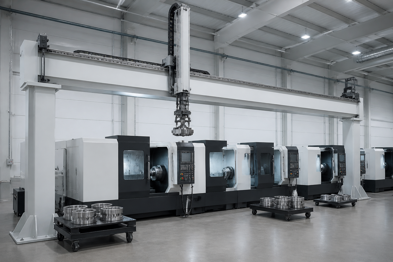
Long-travel gantry over machine tools
Most rack drive problems start with a module picked from a photo of a similar machine. Sizing takes four steps and one page of arithmetic.
Step 1 - Force at the rack
Add acceleration force, friction and any gravity component: F = m x a + m x g x mu + m x g x sin(incline), then apply a service factor for shocks and duty. Vertical axes carry the full weight continuously and need a brake and a safety concept that does not rely on the rack drive alone.
Step 2 - Pinion and module
Pinion pitch diameter d = z x m. A larger pinion lowers tooth force for a given torque; a larger module gives a stronger tooth. Check the module against the rack maker's permissible tangential force tables, and stay at or above about 17 teeth unless the pinion is profile shifted.
Step 3 - Torque
T = Ft x d / 2. This is the torque the gearbox output must deliver at peak acceleration.
Step 4 - Speed
Pinion speed n (rpm) = v (m/min) x 1000 / (z x pi x m). The gearbox ratio follows from motor speed / n.
Worked example
| Input | Value |
| Moving mass | 500 kg (horizontal) |
| Acceleration | 2 m/s^2 |
| Friction coefficient (linear guides) | 0.01 |
| Speed | 60 m/min |
| Service factor (assumed) | 1.5 |
| Result | Calculation | Value |
| Acceleration force | 500 x 2 | 1000 N |
| Friction | 500 x 9.81 x 0.01 | 49 N |
| Design force | (1000 + 49) x 1.5 | 1574 N |
| Pinion | M3, 20 teeth, d = 60 mm (spur) | |
| Torque | 1574 x 0.060 / 2 | 47.2 N.m |
| Pinion speed | 60 000 / (20 x pi x 3) | 318 rpm |
For a helical rack, use the transverse pitch: with 19 deg 31' 42" and M3, the pinion travels 20 x 10 = 200 mm per revolution, so 60 m/min needs 300 rpm and d = 63.66 mm.
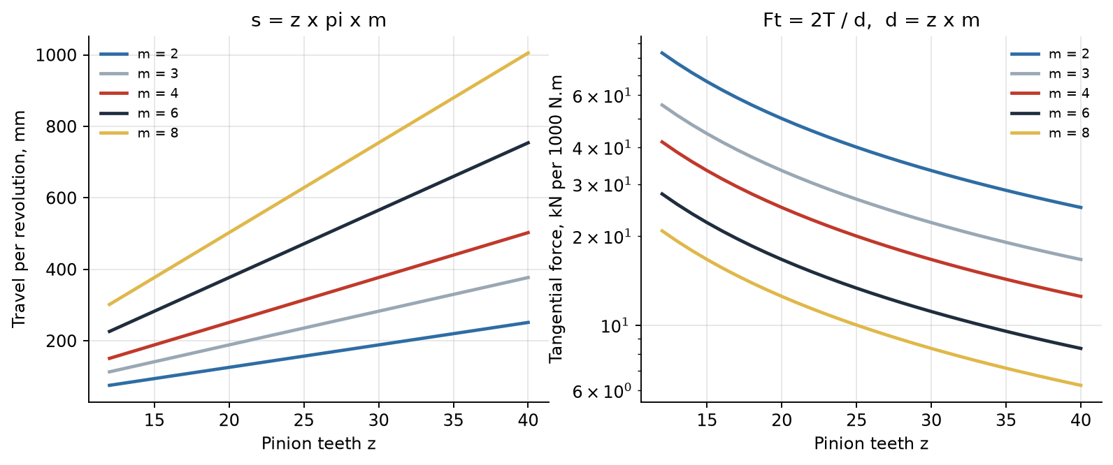
Tooth force and travel per revolution against tooth count and module
Checks before ordering
· Tangential force against the rack and pinion rating at the chosen grade and hardness.
· Pinion bearing loads, including axial force for helical teeth (Fa = Ft x tan beta).
· Rack mounting: bolts and dowels sized for the peak force.
· Backlash at the chosen grade versus required positioning.
Summary
Force, module and pinion, torque, speed. Send us the four inputs and we will propose the rack, pinion and grade.
For drawings, samples or a quotation, send us your rack, pinion or gear specification and quantity.
