 EN
EN

A construction hoist is one of the few machines where a gear tooth failure kills people. That single fact changes how the rack and pinion has to be specified, inspected and replaced, and it explains why the maintenance numbers in this article are absolute dimensions rather than the percentage wear limits used elsewhere in power transmission.
We supply racks and pinions into this sector, and the questions we get from hoist builders and site maintenance teams are always the same three: when is a rack worn out, what backlash is correct, and how do the safety device and the drive pinion share the load. Here are the answers with the actual numbers.
EN 12159 is the European standard for builders hoists for persons and materials with vertically guided cages. It covers permanently installed and temporarily installed hoists serving defined landing levels, with a driver or automatic control, and it applies to hoists used on construction sites for people and goods.
The standard matters commercially because a hoist sold into the EEA has to meet it. That flows down to component suppliers: rack material, tooth quality and traceability all become part of the machine file.
In North America the equivalent is ANSI/ASSE A10.4, Personnel Hoists and Employee Elevators on Construction and Demolition Sites. It is a different document with a different structure, and it is worth noting that ISO 16368, which gets cited in this context sometimes, actually covers mobile elevating work platforms rather than mast climbing hoists. They are not interchangeable references.
Standard SC-class hoists run module 8 racks. This is consistent across the OEM documentation we work from, for both the drive pinions and the safety device pinion.
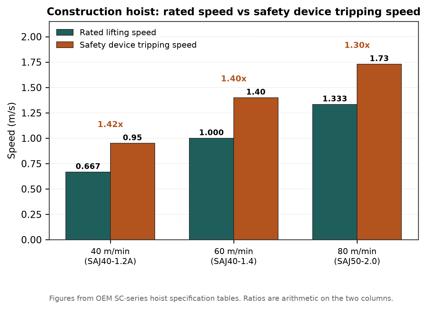
Safety device tripping speed sits roughly 30 to 40 per cent above rated lifting speed.
A typical SC200/200 drive is built from two or three sets of motor, coupling, reducer and pinion, all engaging the same rack, with the safety device carrying its own pinion on a separate shaft. Motor power is quoted in the OEM tables in the form "16.5 kW x 2" or "24 kW x 3", which tells you directly how many drive units are fitted. The safety device pinion has 15 teeth in the common SAJ30/SAJ40 configuration, though 12-tooth versions exist.
Racks are mounted in sections bolted to each mast section, so a 100 metre mast is a stack of spliced racks. Splice quality determines whether the pinion climbs smoothly or hammers at every joint.
This is where most site problems begin.
The OEM instruction is explicit about the consequence of getting it wrong:
If the backlash is too small or too big, it will result in meshing interference, abnormal vibration and noise, and will even damage the safety device.
Too tight and the teeth interfere, heat up and pick up. Too loose and the pinion impacts each tooth flank instead of rolling into engagement, which is what produces the hammering noise you hear on badly maintained hoists, and what accelerates rack wear.
The engagement geometry is set by the guide rollers, not by the rack bolts. If the rollers are worn the pinion sits at the wrong centre distance, and no amount of rack adjustment fixes it. This is why the wear limits below include the rollers.
Site teams usually ask for a percentage. The OEM service data does not work that way; it gives absolute dimensions and a measurement method for each.
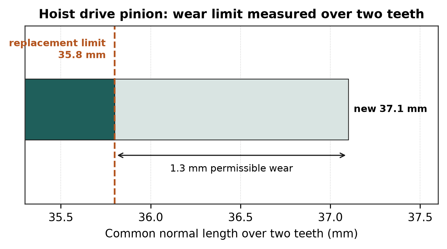
Drive pinion wear limit, measured as common normal length over two teeth.
Drive pinion, measured over two teeth with a common normal micrometre:
| Condition | Common normal length over two teeth |
| New tooth | 37.1 mm |
| Most worn tooth, replacement limit | 35.8 mm |
That is 1.3 mm of permissible wear, about 3.5% of the new dimension. The percentage is arithmetic on the two published figures; the manual itself states only the millimetre values, and the millimetre values are what you measure against.
Rack: measured with a 18 mm diameter standard round bar and a sliding caliper. The gauge pin sits in the tooth space and you measure to a datum. Note that this is a go/no-go style check against a figure in the OEM drawing for your specific hoist, so take the limit from your own machine documentation rather than assuming a generic value.
Worm (in the drive gearbox):
| Condition | Value |
| New tooth | 70 mm |
| Most worn tooth | 67.9 mm |
| Maximum allowable wear | 1.0 mm |
Guide rollers, 76 mm section columns:
| Measurement | New | Worn limit |
| A | 74 mm dia | Min 69 mm dia |
| B | 75.5 mm | Min 73 mm |
| C | R38.5 | Min R38, max R42 |
For high speed and frequency controlled hoists the A dimension is 80 mm new with a 75 mm limit, and B is 78.5 mm new with a 76 mm limit. For 89 mm section columns, A is 78 mm new with a 73 mm limit.
Safety device shaft radial clearance has its own replacement trigger, and it is the one most often skipped because it needs a fixture. Clamp a measurement support about 1.0 mm above the gear, measure the clearance to the tooth crest, lift the gear with a lever without rotating it, and measure again. The difference is the radial clearance.
If the clearance is more than 0.6 mm, replace anti-falling device.
Not adjust. Replace.
The SAJ progressive safety device is the component that stops a falling cage. It was developed by the Shanghai Research Institute of Building Sciences and passed Ministry of Construction identification in 1989, and the design has been the sector standard since.
Mechanically it is a pinion driving a centrifugal mechanism: eccentric masses, a butterfly spring, an outer cone and an inner tapered drum. Above a set speed the masses fly out, the cone engages, and the device brakes the cage against the rack it is already meshed with.
Rated braking loads by model:
| Model | Rated braking load | Rated braking speed |
| SAJ30 | 30 kN | 0.5 to 1.6 m/s depending on variant |
| SAJ40 | 40 kN | 1.2 to 2.0 m/s |
| SAJ50 | 50 kN | 1.2 to 2.0 m/s |
| SAJ60 | 60 kN | 1.2 to 2.0 m/s |
| SAJ70 | 70 kN | 1.4 m/s |
The useful engineering relationship is between rated hoist speed and the speed at which the device actually trips. From OEM hoist specification tables:
| Rated lifting speed | Safety device | Tripping speed | Ratio |
| 40 m/min (0.667 m/s) | SAJ40-1.2A / SAJ30-1.2 | 0.95 m/s | 1.42x |
| 60 m/min (1.0 m/s) | SAJ40-1.4 | 1.4 m/s | 1.40x |
| 80 m/min (1.333 m/s) | SAJ50-2.0 | 1.73 m/s | 1.30x |
So the trip point sits roughly 30 to 40% above rated speed. An independent industry source gives the general band as 1.2 to 1.4 times rated speed, which matches.
Catching distance, meaning the distance from the device responding to the cage stopping, is specified as 0.15 to 1.0 m in the OEM manual. A safety device supplier quotes 0.3 to 1.2 m excluding free descent. Either way, a cage that stops within a metre is behaving correctly.
Twin devices must be matched. Where two safety devices are fitted, the OEM requirement is that the difference in tripping speed should be no more than 0.05 m/s, both when resetting and when replacing. Replace them as a pair.
This is the one legal obligation most often compressed on site.
For each hoist first used, or newly built after transferred to another place, must have a falling test with rated load before normal use. After normal use, have this test once 3 months, to ensure safety of the hoist.
Three independent sources agree on the three month interval; one adds "or every 1,000 operating hours, whichever comes first."
The test is run at rated load, with all personnel out of the cage, using a dedicated drop test button box plugged into a socket at the bottom of the cage control box. Two practical constraints worth knowing:
· No two drop tests within 15 minutes. The device overheats.
· The safety device has a 5 year effective service life and requires annual inspection regardless of use. OEM maintenance schedules call for replacement at least once every 3 years depending on condition.
Lubrication is every 120 working hours with No.2 lithium base grease.
Rack and mast fasteners are property class 8.8 as standard. Torque values are published per joint in the hoist manual and vary by bolt size and whether the surface is galvanized and dry. Do not substitute a generic torque chart; the mast joint torques in particular are specific to the section design.
What matters more than the absolute figure is re-checking. Mast bolts relax during the first weeks of service as the structure settles, and a loose rack splice shows up as a pitch error at the joint, which the pinion then hammers.
Three things separate a rack that works from one that causes trouble:
1. Consistent splice geometry. Every joint is a potential pitch error. Racks cut and finished as a matched set behave better than racks pulled from random stock.
2. Hardness consistency along the length. Soft spots wear early and locally, and local wear is what puts a rack past the gauge limit while the rest of the bar is fine.
3. Documented material and heat treatment. For a machine covered by EN 12159 this goes in the technical file, and a supplier who cannot produce it creates a compliance problem for the hoist builder.
We manufacture module 8 racks for this application in our own plant, cut and heat treated in house, which is what lets us hold splice geometry across a batch.
Can I replace just the worn rack sections?
Yes, and it is normal practice, provided the replacement matches the existing rack in module, tooth quality and mounting geometry. Mixing rack from different sources on one mast is where pitch errors at the joints come from.
The pinion measures 36.2 mm over two teeth. Is it scrap?
No. The limit is 35.8 mm, so 36.2 mm is still serviceable, but it is 0.4 mm from replacement. Plan the change rather than waiting for the next inspection.
Why does the safety device have its own pinion instead of using the drive pinion?
Because it has to work when the drive fails, including when a drive pinion shears or a gearbox fails. Independence is the point.
Is the 3 month drop test interval negotiable if the hoist is lightly used?
The OEM states 3 months after normal use begins. Some industry guidance adds a 1,000 hour alternative, whichever comes first. Local regulations may be stricter. Treat 3 months as the default and check your jurisdiction.
How much backlash should I set?
Take it from your hoist manual for the specific model. The general rule is that it must be neither tight enough to interfere nor loose enough to allow impact. If you hear hammering under load, it is too loose or the guide rollers are worn.
Does a worn rack damage the safety device?
It can. The safety device pinion meshes with the same rack. Excessive backlash from a worn rack means the safety device pinion also runs with poor engagement, and the OEM specifically warns that incorrect backlash can damage the device.
Tianjin HaoRongShengYe Electrical Equipment Co., Ltd. has manufactured gear racks, pinions and transmission components since 2008. We supply module 8 racks and matched pinions for construction hoist applications, cut and heat treated in our own plant so splice geometry stays consistent across a batch. Send us your mast section drawing and rated load and we will quote a matched set.
